
- ARDUINO RELAY LIGHT INSTALL
- ARDUINO RELAY LIGHT SERIAL
- ARDUINO RELAY LIGHT SOFTWARE
- ARDUINO RELAY LIGHT CODE
- ARDUINO RELAY LIGHT FREE
We have to change the baud rate because we need it to be higher than the MIDI’s baud rate, which is 31250. Then, go to File > Preferences > Set the Baud rate to 38400 > OK.
ARDUINO RELAY LIGHT SERIAL
Then open Hairless Serial to MIDI bridge and select the Arduino port as the serial port and MIDI in port as loopMIDI. Setting the Baud Rate Connect the lights and power to the relay board and connect the Arduino to your computer. * Similarly, '2' is returned for D3(note 64), etc. * For eg, C3(note 62) corresponds to the first light,

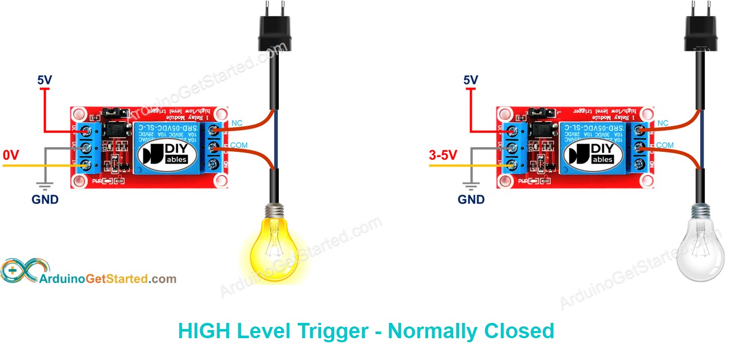
* So, this function will return the number of the bit * (sharp notes are excluded) (total 24 lights) * The range of music notes used for the control *Which bit has to be turned ON or OFF is found turn on the lights according to the new data ShiftOut(dataPin, clockPin, MSBFIRST, lightData1) ShiftOut(dataPin, clockPin, MSBFIRST, lightData2) ShiftOut(dataPin, clockPin, MSBFIRST, lightData3) set the corresponding bit in lightData so that lights don't change while the new data is being shifted the lights are set according to the data on MIDI ch.1 Pin connected to Data in (DS) of 74HC595īyte lightData1 = 0, lightData2 = 0, lightData3 = 0 // Pin connected to clock pin (SH_CP) of 74HC595 Pin connected to latch pin (ST_CP) of 74HC595 * ST_CP (pin 12) to Ardunio DigitalPin 10 (green wire) * SH_CP (pin 11) to to Ardunio DigitalPin 8 (yellow wire) * DS (pin 14) to Ardunio DigitalPin 9 (blue wire) * This project was inspired from a YouTube video by John Storms The set at the right consists of VCC and GND to power up the module, and input 1 ( IN1) and input 2 ( IN2) to control the bottom and top relays, respectively. Pin wiring The low-voltage side has a set of four pins and a set of three pins. * My blog: /1/the-arduino-lights-project/ If you just want to light up a lamp occasionally, it is better to use a normally-open circuit configuration. * Christmas New year light show with Arduino Go to ‘External Devices’ >Add > New Instrument > Send to: loopMIDI port > OK > OK Set up the loopMIDI port as a new instrument in the DAW software.Run loopMIDI and start a virtual MIDI port.
ARDUINO RELAY LIGHT INSTALL
ARDUINO RELAY LIGHT FREE
Most of the features work in the free version. Install Studio One (or any DAW software).If there is any connection, it can destroy the Arduino and ICs. PLEASE NOTE: If you are powering the relay board with 12V, make sure that there is no connection (by accident) between the external relay board Vcc (12V) and the 5V on the relay board (remove the jumper seen in most relay boards). Since it is not recommended to draw the power needed for working on relays from the Arduino board. Now get ready to build your own Christmas light show with Arduino! Building the Circuit for Our Christmas Light Show With Arduino Set up the circuit as shown in the diagram and connect an external relay power source. After all the bytes are sent and the process is finished, they are latched, which prevents the relays from turning on/off while shifting the data. The three bytes are shifted out of the registers and then are latched on so the relays turn on/off.
ARDUINO RELAY LIGHT SOFTWARE
The music software sends out the MIDI data, which is received by the Arduino and sets the corresponding bit of one of the three bytes to 0 or 1. Three bytes are used to store the light states in the program (on/off). The t hree 74HC595s are used to control the relays. At 150☏ the relay shuts off and the current stops.The lights are connected to the relays on the relay boards.

In this example, the relay will stay activated and let current flow through the light bulb until the temperature of the thermistor reaches 150☏.
ARDUINO RELAY LIGHT CODE
The CodeĪfter everything is connected, upload this code to the Arduino: #include See our article on Making an Arduino Temperature Sensor for more information. If you do use a 100K Ω thermistor, you’ll need to change line 7 in the code below to Temp = log(100000.0*((1024.0/RawADC-1))). If you use a 100K Ω thermistor, use a 100K Ω resistor. For example, I’m using a 10K Ω thermistor, so the resistor should be 10K Ω as well. The value of the resistor should be the same order of magnitude as the thermistor. The thermistor part of the circuit is set up as a voltage divider. It’s dangerous to put the relay on the neutral wire, since if the device fails current can still fault to ground when the relay is off. This way the relay is on the hot side, and current is switched before it reaches the light bulb. Connect the side leading to the light bulb to the NO terminal of the relay, and the side leading to the plug to the C terminal. Identify the hot power wire (red wire in the diagram above) in the cord leading to the light bulb and make a cut.


 0 kommentar(er)
